

It is vital to know the exact operating point conditions in order to be able to assess the impacts of viscosity differences realistically in the fields of plastics extrusion and injection molding. Furthermore, information about the operating conditions allows you to determine the size of the measurement window for testing. The process-determining factor is the shear rate. The actual shear rate is determined from geometry parameters and the volume flow. An estimation as a guideline for various processes and measuring instruments is shown in the following diagram.
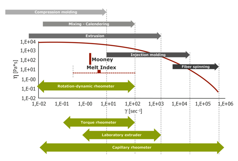 Shear rate - measuring and processing ranges
A more detailed analysis than the estimation in the diagram above is provided by a numerical calculation of the shear rate in the respective melt flow-way of the process as a function of geometry and volume flow. In this case, the shear rates in melt flow-ways can either be determined in a complex manner through simulation programs or be approximated quite well using simple models. The latter method offers a simple way to determine the shear rate or shear rate range at which the measurement is performed and which can be used for effective material selection to compare the viscosity of various materials at the respective shear rate or shear rate range of the operating point.
These simple models are:
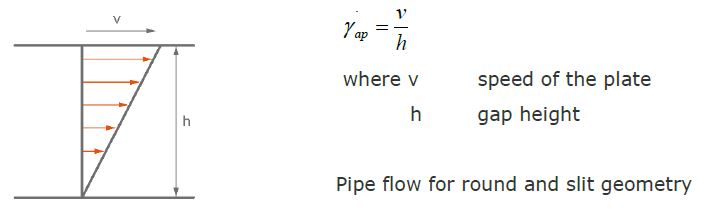
Two-plates model for a gap with a moving plate:
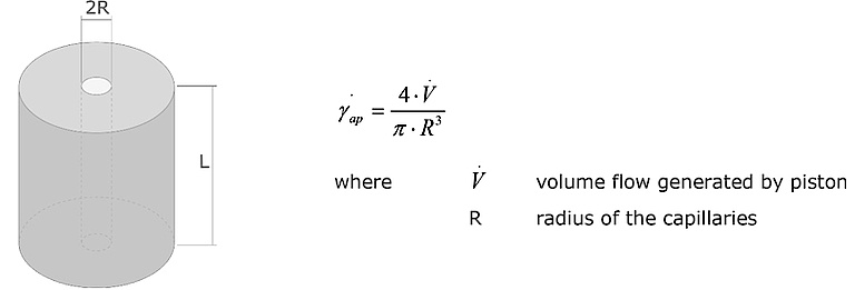
Round hole die: Apparent shear rate: GAMap [s-1]
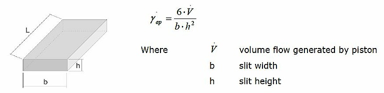
Slit die: Apparent shear rate: GAMap [s-1]
The two-plates model can be used to estimate the shear rate in the screw section of an extruder.
The speed of the moving plate v results from the screw diameter and the extruder speed as
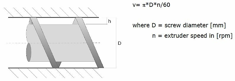
And the shear rate results from
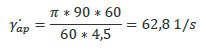
Example: For a 90mm extruder, the apparent shear rate results from a thread depth of 4.5mm in the zone close to the head and at a speed of 60rpm:
The respective pipe die has the following geometry:
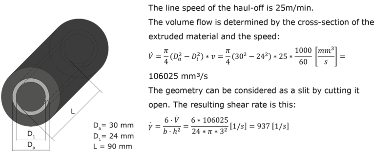
This information can then be used to analyze any material differences in the shear rate range around the operating point.
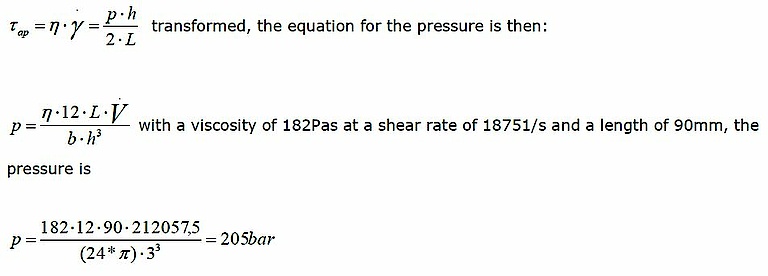
If the length of a parallel melt flow-way in a die or die segment is known, a rough estimate of the extrusion pressure can also be made with the aid of the viscosity measurement using the following equation:
 Extrusion die
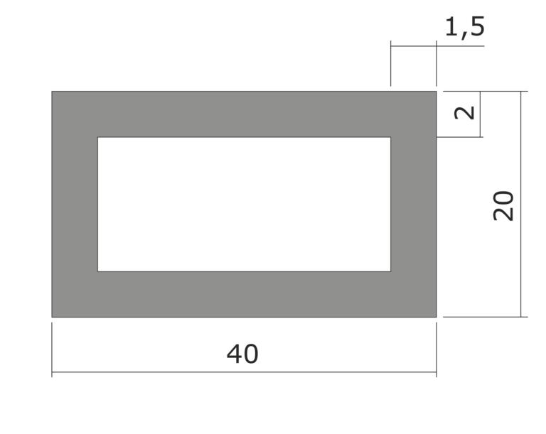
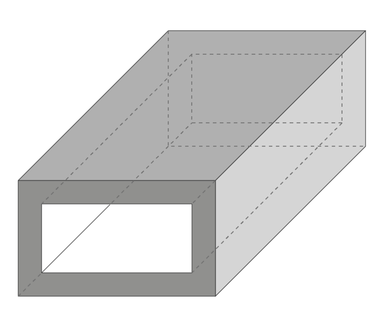 Extrusion profile
The line speed v of the haul-off is 15m/min
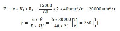
The die is initially divided into slit segments. For each segment, the volume flow is calculated as V = v * Hi * Bi for segment i=1 or 2.
Segment 1:
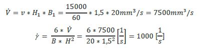
Segment 2:
As shown by the calculations, even a simple examination allows an effective estimation of the operating point with the following advantages: