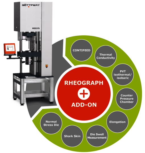
GÖTTFERT is able to provide two process-related options for the pressure-dependent determination of the viscosity function:
The counter pressure chamber is an established standardized Add-on feature for the GÖTTFERT capillary rheometer. An innovative additional development is the counter pressure viscometer, which consists of two coupled capillary rheometers.
A long-established Add-on for capillary rheometers is the counter pressure chamber, with that Add-on the pressure conditions behind the capillary can be measured. The modular measurement device is designed like a conventional capillary rheometers with corresponding pressure transducer (P1) and capillary. After the capillary, a counter pressure chamber is installed, which makes it possible to simulate different pressure levels. A manually adjustable choke below the capillary increases the pressure at the capillary outlet. However, the pressure to be set depends on the flow and can not be regulated.
Therefore, a considerable amount of experimental effort is required with many measurements until the viscosity function at the desired counter pressure can be determined. To measure this counter pressure, a second pressure transducer (P2) is necessary. In the next step, the software of the instrument is calculating the counter pressure coefficient.
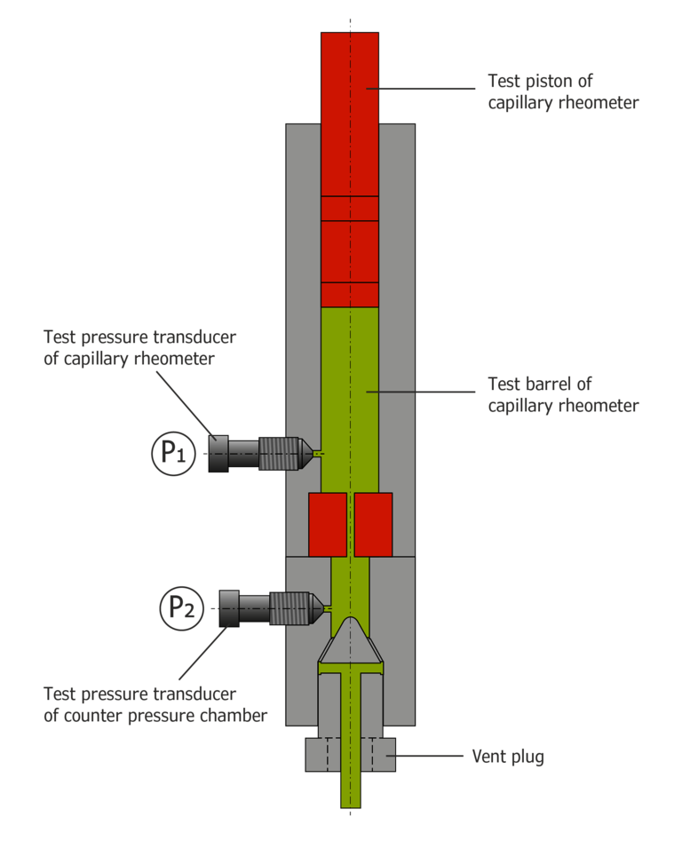 Figure 1: Capillar Rheometer with Add-on Counter Pressure Champer
Such a counter pressure chamber made it possible to measure the flow characteristics of polymers in the range of their processing conditions.
However, the measurement of the viscosity at the desired counter pressure requires a very high experimental effort.
An innovative, more efficient way to measure the pressure-dependent viscosity of plastics in processing is the counter pressure viscometer.
The counter-pressure viscometer consists of two coupled capillary rheometers. The barrels of these rheometers are connected to each other via a counter pressure barrel. Barrel (1) is the one in which the viscosity measurement takes place.
At the end of the barrel is a capillary to measure the viscosity. Barrel (2), the generated counter pressure is controlled by the pressure sensor (P2). Barrel (1) and barrel (2) of the counter pressure viscometer are connected to each other via a counter pressure chamber.
The sequence of the measuring process can be compared with conventional viscosity measurements with capillary rheometers.
Barrel 1 is filled with polymer granules. After the material is melted homogeneous, a constant counter pressure will be controlled via pressure transducer 2 as well as barrel 2. So the viscosity measurement can be carried out in dependance to a controlled counter pressure. With such a counterpressure viscometer, flow curves at different counter pressure can be carried out in an automatic way. After the first flow curve has been measured, the material from barrel 2 is pushed back into barrel 1. Subsequently, another flow curve can be measured at a different counter pressure.
The counter pressure viscometer offers the option of measuring cycles to carry out fully automatic viscosity functions fully at different pressure levels. Barrel (2) is controlling the counter pressure. After a flow curve has been determined, the material of capillary rheometer 2 is pressed into the barrel of capillary rheometer 1. Subsequently, another further flow curve can be measured at a different counter pressure. Figure 2 shows an example of a PE-HD at counter pressures of 100, 500, 1000 and 1500 bar. The flow curves are shifted due to the counter pressure against each other. The measured data can then be shifted to a master curve.
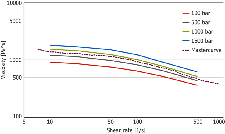 Figure 3: Viscosity function with different counter pressure
With the counter pressure viscometer, the measuring cycles at different counter pressure levels can be carried out fully automatic
This is particularly an advantage when data is to be determined above the melting point of the polymer, or when shear-induced crystallization occurs. In a counter pressure chamber, the pressure loss through the capillary would be increased in such a measurement. Also, the flow resistance through the throttle would be so strong that not constant measuring conditions can be set. Therefore, counter pressure measurements with the counter pressure chamber are very difficult to execute.
Counter pressure rheometry, the prerequisite for analyzing the flow behavior of PP and PET under processing conditions in the event of shear-induced crystallization!
The counter pressure viscometer has the great advantage that the counter pressure as well as the conditions oft the measurement can be kept constant. The instrument offers the possibility of analyzing polymers, such as PP or PET, with shear-induced crystallization. This increases with increasing shear rate in the process-relevant area.